← notes / 2025.12.07
build log: singing tesla coil
the idea was a speaker with no cone and no voice coil. a tesla coil throws electrical arcs that ionize the air around them, and ionized air makes noise, kind of the same way thunder does. pulse those arcs at different frequencies and you get notes.
what we wanted was something you could hand an mp3 or a wav or whatever, and hear that file come back out of the arcs. turns out it isn’t nearly that simple, but that was the goal.
this was a 4 person course project (enes-100 at howard cc), so credit where it’s due. i worked mostly on the hardware. winding the coil, hunting down the proof of concept and other real builds to work from, the design and marketing side, and the circuit diagram. the arduino code and the teensy integration were other people’s work, and the switch in how the audio got processed happened without my input.
where the design came from
the main reference was this arduino musical tesla coil build, which runs on a slayer exciter. a slayer exciter is about the simplest solid state tesla coil there is, basically a primary, a secondary, and a switching transistor, and our design drew heavily from it.
being honest about it, we were mostly trying to clone somebody else’s results. there’s a lot published on this stuff and we leaned on all of it. what we didn’t do was the math and the physics that this actually needed. a lot of it was winging it with parts and hoping we’d matched the guy in the link closely enough by chance.
the coil
17 inch pvc pipe, 1 inch diameter, with roughly 1,650 turns of thin copper for the secondary and 6 turns of 26 gauge for the primary. i wasn’t counting turns as i went, that number is just what the math worked out to. the dimensions came from an existing build that produced about the volume we were going for, and we adjusted from there. winding that many turns by hand is exactly as tedious as it sounds, and it ended up mattering more than i expected.
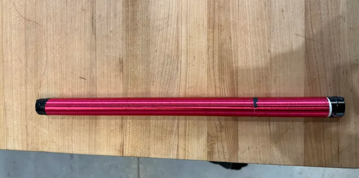 the finished secondary. roughly 1,650 turns of copper on a 17 inch length of pvc.
the circuit
this is the part i drew up. the diagram takes pwm off an arduino uno, sends it through a 4n35 optocoupler, and uses that to drive a pair of tip31c transistors switching the primary. 6 turns on the primary, roughly 1,650 on the secondary, 18v on the coil side, spark gap at the top.
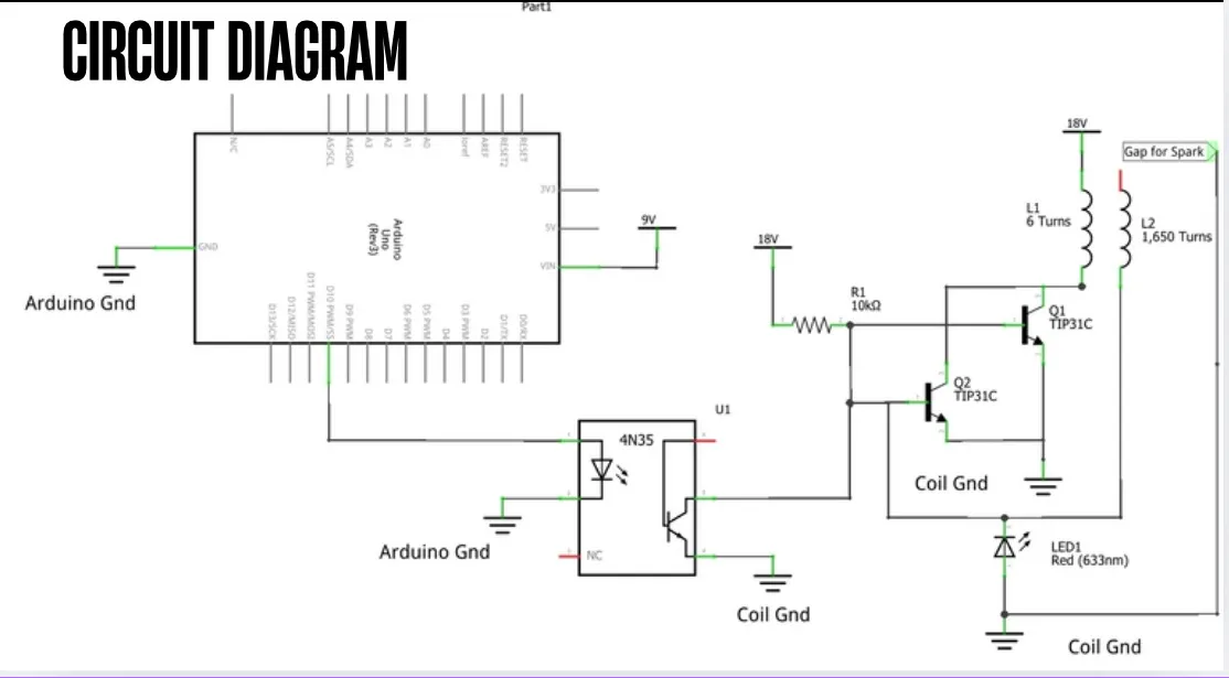 arduino on the left, 4n35 optocoupler in the middle, the two tip31cs switching the coil on the right. the two grounds never touch.
the optocoupler is the piece that matters most. the arduino side and the coil side sit on completely separate grounds, drawn that way on purpose, and the optocoupler passes the signal across as light. that way a spike coming back off the coil has nothing to travel down into the arduino.
our version differed from the reference because we had an arduino and a computer in the loop for the audio libraries. i didn’t know much about circuits at the time (still don’t know as much as i’d like) so i used chatgpt to help bridge the gap between the reference design and what our specific attempt actually called for.
the parts list changed after that. the final build ended up on a 6n137 optocoupler and an irlz44n mosfet at 12v, with a her108 flyback diode across the coil to eat the voltage spikes. the reasoning in the report is that the original picks wouldn’t keep up with the voltage and switching speed. that came in alongside the move to the teensy, which wasn’t my call.
the base had to hold the coil far enough off the circuit board that the magnetic field wouldn’t mess with the components sitting next to it.
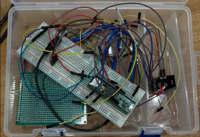 prototyping on the breadboard.
the shield we didn’t build
the original sketch had a petg shield wrapped around the coil, and it made it into the report as part of the final concept. we cut it and went open air. the arcs were small enough that we weren’t worried about them, and the petg would have either melted, gotten in the way of the performance, or eaten time we didn’t have. the rgb lights stayed.
how it actually ended
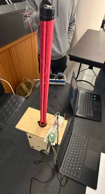 set up at projects night. the base keeps the coil clear of the circuit board underneath.
it never made a sound. the circuit got built and parts of it worked, but by the deadline there was no audio coming out of it. the secondary coil was the main suspect, since a messy wind or a single break in the wire will wreck it, and mine was not a clean wind. the projects night presentation also landed earlier than we planned for, which took a chunk out of the time we had to chase it down.
looking back, the coil was the visible problem but not the whole one. we copied a build instead of working out why that build’s numbers were what they were, so when it didn’t sing we had no math to tell us where to look. tuning was the thing everyone kept pointing at and nobody had the tools to actually fix it.
what i’d do different
- do the math. work out the resonance and the tuning instead of matching somebody else’s build and hoping
- order parts earlier. we underestimated what some of the components could handle and had to go back for the right ones, which cost real time
- wind the secondary slowly and uniformly the first time, with no breaks
- keep the wiring short, long runs distort the audio
- the report flagged the mosfet heatsink as undersized and worth upgrading, though it never actually became a problem we ran into